III. Annex
1. Research
1.1. Relay
A relay enables a signal of electricity (I would call it controlling signal) to switch on or off a separate flow of energy. A relay contains a coil, an armature, and at least one pair of contacts. Current flows through the coil, which functions as an electromagnet and generates a magnetic field. This pulls the armature, which is often shaped as a pivoting bracket that closes (or opens) the contacts. [1]
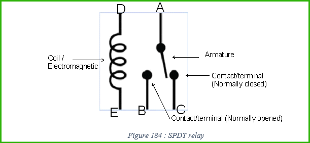
More Specifically, by considering a SPDT[2] relay (Single Pole Double Throw) the two terminal D & E are connected to the signal (one to positive and one to negative, orders are not important). Depends on purpose, A, B, C can be connected differently. When there is no signal, terminal A is connected to terminal C, therefore terminal C is called normally closed, and B is called normally opened. When there is a signal passing through the coil, the armature will be pulled so that terminal A is connected to terminal B.[3]
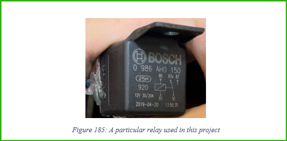
From Figure 185, 85, 86 are similar to D, E; 30 is similar to A; 87 is similar to B; and 87c is similar to C.
1.2. Dc-Dc converter
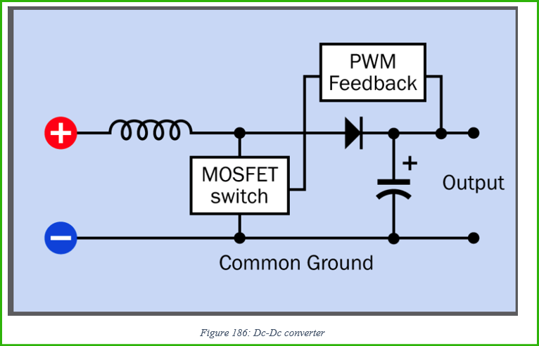
Some unusual components:
- Mosfet switch: Metal Oxide Semiconductor Field-Effect Transistor.
- PWM feedback: Pulse Width Modulation feedback. In PWM feedback, a portion of the output voltage or current is compared to a reference value, and the resulting error signal is used to adjust the duty cycle of a PWM signal. The duty cycle refers to the ratio of the on-time of the signal to the total period. By changing the duty cycle, the average value of the PWM signal can be modified, which, in turn, affects the output voltage or current.
Process:
- Switch-on stage: Initially, the MOSFET switch is turned on. This allows current to flow through the inductor and builds up magnetic energy in the inductor. The inductor stores energy in its magnetic field and causes the current to increase gradually.
- Switch-off stage: The MOSFET switch is turned off, interrupting the current flow through the inductor. At this point, the energy stored in the inductor’s magnetic field seeks a path to discharge. The diode, also known as the freewheeling diode, allows the current to flow through the inductor, the diode, and the load, creating a closed loop.
- Inductor discharge stage: As the current flows through the diode, it charges the output capacitor and powers the load. The inductor discharges its stored energy during this stage.
- Voltage step up: the voltage of the load after the Mosfet switch is turned of is the sum of the voltage of the capacitor and of the inductor. Therefore, the voltage reaching the load is increased. The diode is here to stop the current from the capacitor to flow back to the battery, as its voltage is now higher than the battery voltage.
- PWM Feedback: To regulate the output voltage, a feedback control mechanism is employed. A fraction of the output voltage is compared to a reference voltage, and the resulting error signal is fed back to a PWM controller. The PWM controller adjusts the duty cycle of the PWM signal to the MOSFET switch, controlling the switching frequency and the duration of the switch-on and switch-off stages.
1.3. High – to – low converter
- A high-to-low level converter, also known as a logic level converter, is a device or circuit that converts a high voltage level to a lower voltage level. It is commonly used when interfacing between systems or components operating at different voltage levels, particularly in digital electronics.
- The purpose of a high-to-low level converter is to ensure compatibility and proper communication between devices with different voltage requirements. For example, if you have a microcontroller operating at 3.3V logic levels and need to interface it with a device that operates at 5V logic levels, a high-to-low level converter is used to convert the 5V signals to 3.3V signals.
- There are various approaches to implementing high-to-low level converters, including the use of voltage dividers, level shifting ICs, and MOSFET-based circuits. Here’s a brief overview of a commonly used method using a level shifting IC:
- Level Shifting IC: A level shifting IC, such as a voltage translator or level shifter, is employed. These ICs are specifically designed to convert signals between different voltage levels.
- Power Supply: The level shifting IC typically requires its own power supply. This power supply voltage is often referred to as VCC, and it should be within the operating range of the IC.
- Input and Output Channels: The high-to-low level converter IC has input channels for high-voltage signals (e.g., 5V) and output channels for low-voltage signals (e.g., 3.3V). The number of channels depends on the specific IC.
- Direction Control (optional): Some level shifting ICs offer bidirectional conversion, meaning they can handle signals in both directions (high to low and low to high). In such cases, a direction control pin is used to select the desired conversion direction.
- Signal Conversion: The high-voltage input signals are connected to the appropriate input channels of the level shifting IC. The IC then converts these signals to the corresponding low-voltage output signals, which can be connected to the target device operating at the lower voltage level.
- It’s important to select a high-to-low level converter that matches the voltage levels and signal requirements of the devices you are interfacing. The datasheet and specifications of the level shifting IC will provide detailed information on the voltage levels supported, signal propagation delay, output drive capabilities, and other relevant parameters.
- Overall, a high-to-low level converter allows for seamless communication between devices operating at different voltage levels, ensuring compatibility and reliable signal transmission.
1.4. Bass
1.4.1. What is bass?
Bass, simply refer to the low frequency, which range from 16 to 256 Hz (C0 to middle C4)”.[4]
1.4.2. What is sub-woofer?
A subwoofer (or sub) is a loudspeaker designed to reproduce low-frequency sound – bass. A subwoofer consist of one or many woofers assembled in a loudspeaker enclosurss. This means there is no treble, middle range in this loudspeaker.
1.4.3. What is speaker diaphragm? Simple structure of a dynamic speaker
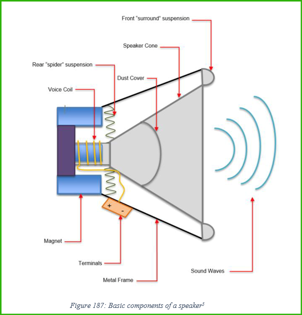
When the Ac signal with a certain frequency is apply between the two terminals, the “voice coil” would act as a electronic magnetic, and would have interactions, either reppelling or attracting to the “magnet”, depends on the direction of the signal, with the frequency depends on the aforementioned frequency of the AC. The voice coil is connected to the diaphragm (equivalent to speaker cone), which will move the diaphragm back and forth (vibrating). (The spider helps the diaphragm move more smoothly). These vibrations move the air, create pressure waves, which can be recieved by our eardrums.
We usually see the bass diaphragm move a lot, is that true that because low frequency travel not as “good” or specifically not as far as high frequency and could not pass though obstacles as good as high frequency?
By searching “is that true low freq travel harder than high freq”, the results was sound “absorptions will tend to be higher at higher frequencies, and so the higher frequencies will be absorbed more rapidly than the lower ones.”. Therefore another search with key words “absorbtion high and low frequency” was performed, and I found certain conception which are absorption and annuation.
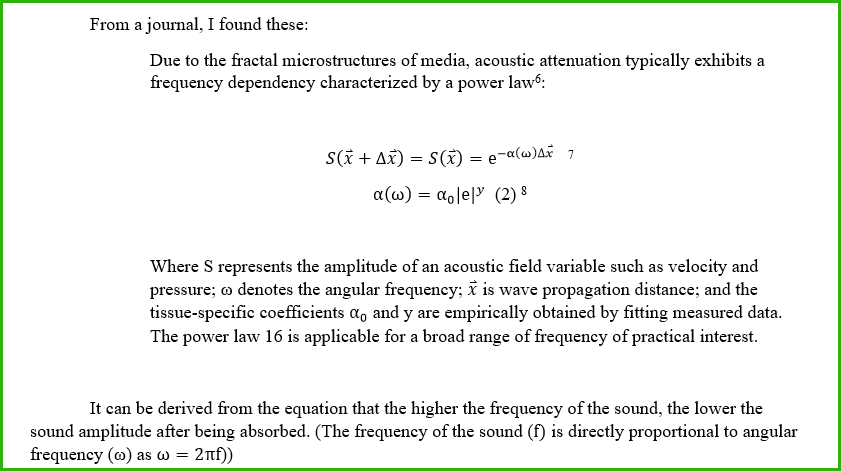
Therefore, the prediction “, is that true that because low frequency travel not as “good” or specifically not as far as high frequency and could not pass though obstacles as good as high frequency?” is not correct. By searching a more simple question “Why bass diaphragm need to move a lot?” I then discovered “The sensitive of our ear to certain frequency” and the “Normal equal-loudness-level contours” which has answered my question.
1.4.4. The sensitive of our ear to certain frequency
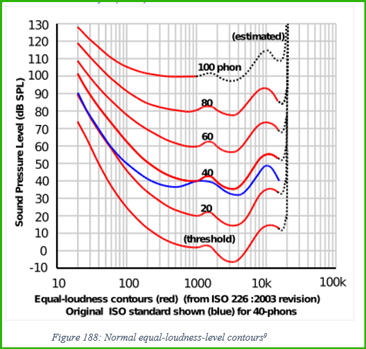
“An ”’equal-loudness contour”’ is a measure of sound pressure dB SPL, over the frequency spectrum, for which a listener perceives a constant loudness. The unit of measurement for loudness levels is the phon”.[10]
It can be derived from the graph that more sound pressure needs to be created at low frequencies to be as loud (to human ear) as high frequencies.
1.4.5. The movement of diaphragm of sub-woofer and cabinet
As aforementioned, more sound pressure needs to be created at low frequencies to be as lound (to human ear) as high frequencies. Therefore, the diaphragm, which create sound pressure (mentioned in 1.4.3 page 105), needs to move a lot to create enough loudness of low frequency for the overall sound to balance with the higher frequency.
1.5. Speaker Enclosure
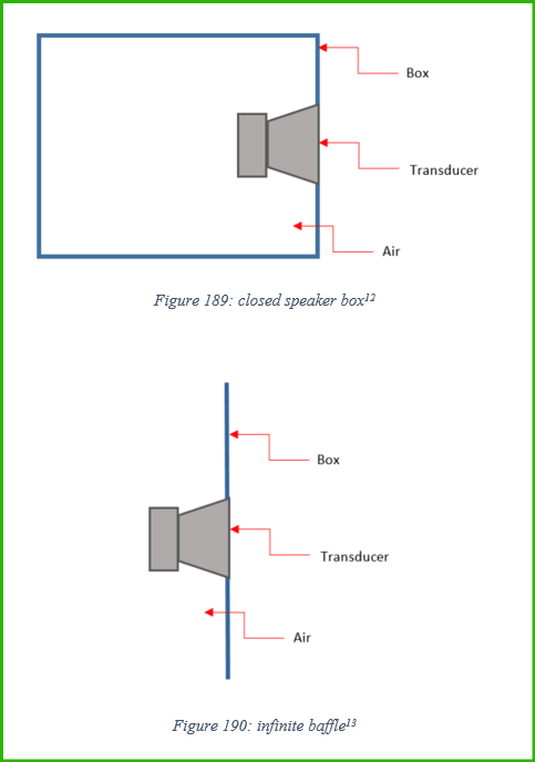
“Many types of enclosures/boxes exist for enhancing/adjusting frequency response from transducers. Some of the most common include the closed box, the infinite baffle, the ported box (bass reflex), and the passive radiator box”[11]
The reasons I choose passive radiator speaker box for my project:
1/ Closed speaker box
The closed speaker box will create a lot of damping, as the air is totally trap inside, therefore when the speaker diaphragm move (for a sub-woofer, it will move a lot, mentioned in 1.4.5 page 108), the air from inside will be compressed and expanded, and therefore there will be a force act on the diaphragm to balance the pressure of air inside and outside the box.
Moreover, ‘sound radiation from the rear of the speaker cone remains entirely shut up in the box, it contributes nothing whatever to the audible output. As a result, exactly half the sonic energy produced by the speaker never reaches the listener’s ears. Such enclosures are inherently inefficient, meaning that only a portion of the amplifier wattage is translated into audible sound’[16].
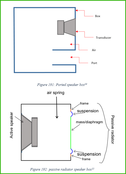
2/ Infinite baffle and ported speaker box
The infinite baffle and ported speaker box are not reasonable choices for my project, as my sub-woofer need to be water resistant, these two types of enclosures are not sealed. Therefore, passive radiator speaker box is the best choice.
3/ Passive radiator box
This fit my project, because it is water resistant (as it is sealed), and it has higher efficient, which will be discussed separately below:
1.6. Passive (bass) radiator
Structure: There are 2 main types of passive radiator
Type 1: With a coil: This structure is similar to a speaker structure, but without terminals and a magnet at the back (see Figure 187: Basic components of a speaker).
Type 2: Without a coil. This type of passive radiator consist of a suspension, a frame, see Figure 193: Passive radiator structure type 2 below:
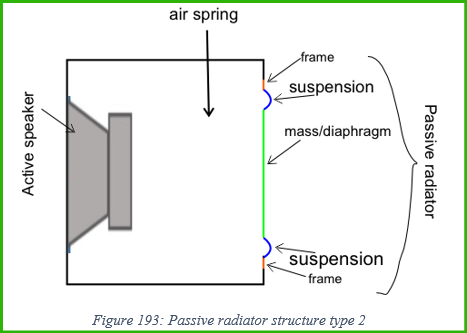
Definition: ‘Passive radiators are components of a speaker system that create more power and resonance in the acoustic experience of the speaker. Passive radiators are commonly used in most speaker systems in order to improve bass quality without having to sacrifice bass. The speakers are called passive because they aren’t being driven by a current or power. Instead, they are driven by air pressure inside of a surround. Another active speaker (direct speaker, using electrical current) in the same box will drive the passive radiator creating sound. Essentially, this passive radiator will enable us to keep a smaller, more compact and low-profile design while not having to sacrifice for rich sound quality.’[17]
As aforementioned, passive radiator will create sound, this sound will mainly be a resonance frequency calculated by these equations:
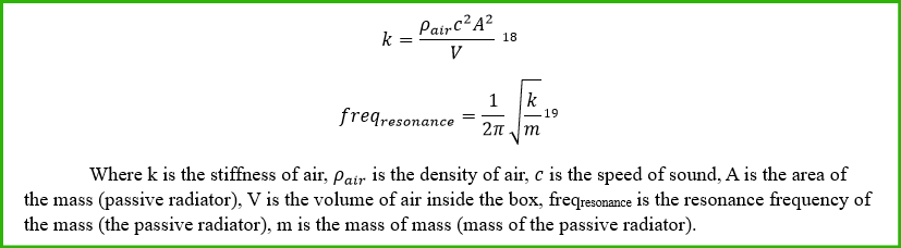
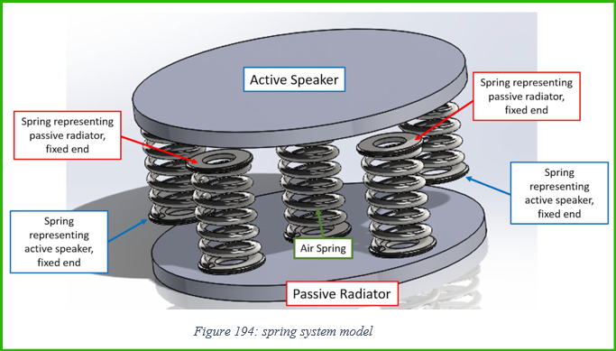
This equation is formed because the air between the active and the passive is considered to be a spring system:
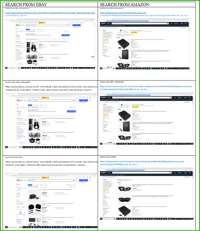
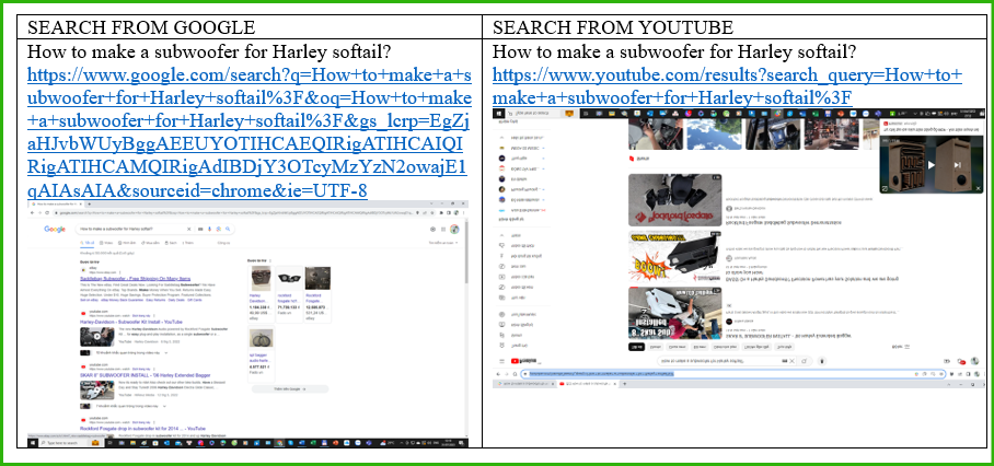
1.7. Evidence of the non-existence of similar product on market:
1.8. Evidence Evidence of the non-existence of tutorial of making same product:
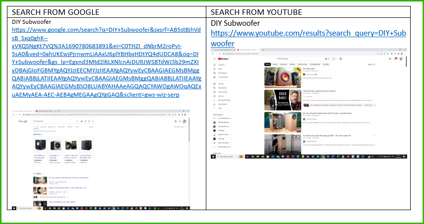
1.9. Researching methods to design and assembly a sub-woofer its own (not optimize for harley)
I will research about how to make a sub-woofer itself, not particularly for harley motorcycle, and then I will learn from that and then desgin and assembly a subwoofer system that suit the Harley
I will research about how to make a sub-woofer itself, not particularly for harley motorcycle, and then I will learn from that and then desgin and assembly a subwoofer system that suit the Harley
[1] (Platt, 2012) Page 143, 144.
[2] Single Pole Double Throw, one input (terminal A) and two switch option (terminal B and C)
[3] (Platt, 2012) Page 147, 148.
[4] (Audio Spectrum, 2020)
[5] (Borsari, Carbonneau, Elsayed, & Honig, The Synthesis and Improvement of a Force Balanced, Sealed Double Passive Radiator Bass Box for a Low Profile Home Speaker System, 2018)
[6] (Chen & Holm)
[7] (Chen & Holm)
[8] (Chen & Holm)
[9] ((ISO), 2003)
[10] ((ISO), 2003)
[11] (Borsari, Carbonneau, Elsayed, & Honig, The Synthesis and Improvement of a Force Balanced, Sealed Double Passive Radiator Bass Box for a Low Profile Home Speaker System, 2018)
[12] (Borsari, Carbonneau, Elsayed, & Honig, The Synthesis and Improvement of a Force Balanced, Sealed Double Passive Radiator Bass Box for a Low Profile Home Speaker System, 2018)
[13] (Borsari, Carbonneau, Elsayed, & Honig, The Synthesis and Improvement of a Force Balanced, Sealed Double Passive Radiator Bass Box for a Low Profile Home Speaker System, 2018)
[14] (Borsari, Carbonneau, Elsayed, & Honig, The Synthesis and Improvement of a Force Balanced, Sealed Double Passive Radiator Bass Box for a Low Profile Home Speaker System, 2018)
[15] (Borsari, Carbonneau, Elsayed, & Honig, The Synthesis and Improvement of a Force Balanced, Sealed Double Passive Radiator Bass Box for a Low Profile Home Speaker System, 2018)
[16] (Fantel, SOUND; The Importance of The Loudspeaker Box, 2023)
[17] (Nyland, Mey, Foley, & McGoff, 2020)
[18] (Nyland, Mey, Foley, & McGoff, 2020)
[19] (Nyland, Mey, Foley, & McGoff, 2020)