II. Implementation (continued)
2.2. Assembly Sub-woofer cabinet:
2.2.1. Removing stuff
Lets refer back to Figure 9: This shows the wiring and struture of the GoHawk Speaker. Below is the recap of it:
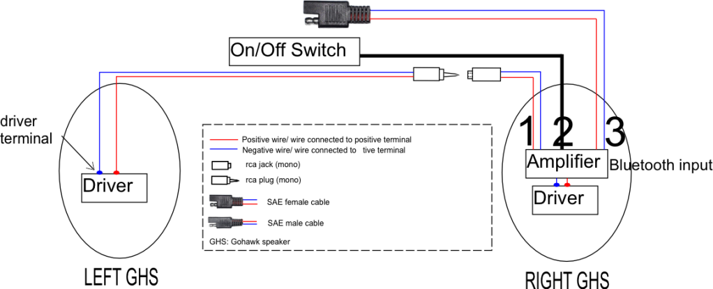
The wires in the left GHS were kept unchanged.
Pair of wires numbered 1 was detached from the amplifier by desoldering. The wire numbered 2, the pair of wires numbered 3 and the amplifier were removed.
The two drivers at both sides were removed.
Figure 48 shows the result. NOTE that the names are now changed to subwoofer instead of GHS.
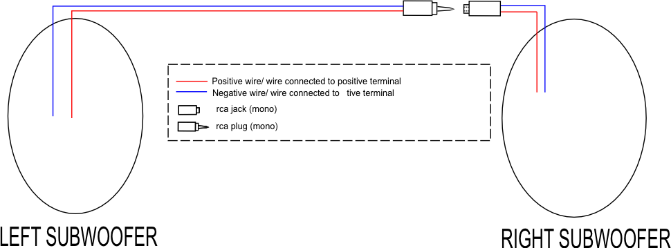
Figure 48: pair of subwoofer cabinet
2.2.2. Others stuff
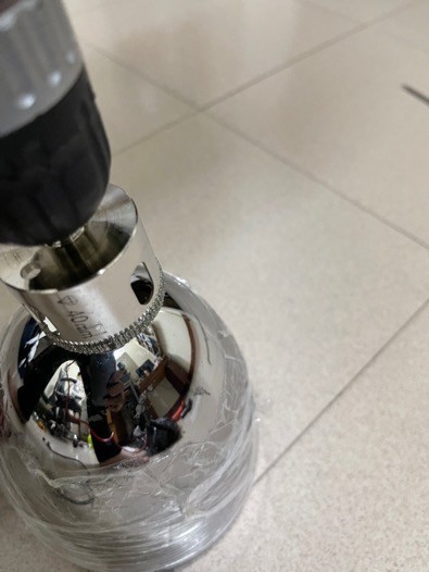
Figure 49
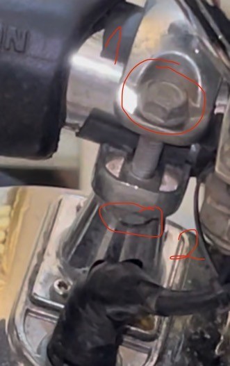
Figure 50
The sub-woofer cabinet having been drilled a 40mm hole (see Figure 49) was attached to the engine guard, by tightening the clamp on the rubber pad lined on the engine guard (the rubber pad function is to avoid slipping) (see Figure 50). To tighten the clamp, I then screwed the screw (numbered 1 in Figure 50) and then screwed the locker (numbered 2 in Figure 50) using 10mm open end spanner (see Screwdriver and wrench (spanner) page 122) (see Figure 51).
Figure 51
Note that this clamp used a screw and a locker (see Screw vs bolt and nut page 123).
A passive radiator was aassembled into the cabinet in the same way as Figure 29 & Figure 30 and the descriptions about these figures).
Speaker driver and amplifier are assembled as in Error! Reference source not found. Page Error! Bookmark not defined., except for passive bass (passive bass and drilling a hole are mentioned already in earlier this section)
The same process was performed on both sides (left and right).
2.3. Set up input signal for the sub-woofer system (music signal):
2.3.1. Summary
The design of input signal of sub-woofer amplifier:
Situation: I had as follows:
- A MP3 with its output was 50mW.
- 4 boss speakers with only one mid-treb amplifier
- 2 sub-woofer speakers with 2 sub-woofer amplifiers
- Maximum amplified signal of mid-treb amplifier is 100W.
- The maximum input power of a mid-treb amplifier was 50mW.
- The maximum input power of a sub-woofer amplifier was 25mW.
The first design:
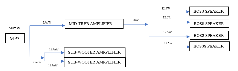
Figure 52: The first design of subwoofer signal input.
The output of the MP3 device was 50mW. With the method, input power of the mid-treb amplifier would be 25mW, and that of the two sub-woofer amplifiers would be 25mW. It meant input power of the mid-treb amplifier, and the two sub-woofer amplifiers would only account for 50% of the MP3 output each, and therefore, the loudness of the Boss system and subwoofer system will both decrease by a half.
The second design:
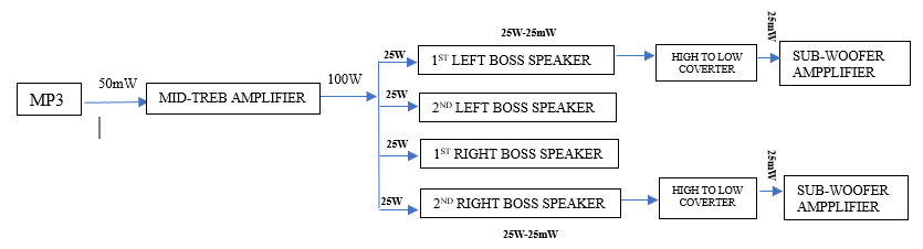
Figure 53: The second design of subwoofer signal input
With this design, input power of the mid-treb amplifier would be 50mW, and that of the two sub-woofer amplifiers also would be 50mW. It meant the input power of the mid-treb amplifier, and that of the two sub-woofer amplifiers could account for the equivalent of 100% of MP3 output each. It also reached the maximum limit of the input voltage of a mid-treb amplifier (50mW), and that of a sub-woofer amplifier (25mW).
The output voltage of the speaker is too high compared to the limit of the input of the amplifier, and to address this issue, I used the high to low signal converter.
Also, I have connected one sub-woofer amplifier to a left boss speaker and another sub-woofer amplifier to a right boss speaker via high to low converter, so in case the left boss speaker or right boss speaker was off (due to the arrangement of the song), there would still be a working sub-woofer amplifier.
Comparing the two designs above, of course, I chose the second one.
The overall wiring for input signal for sub-woofer
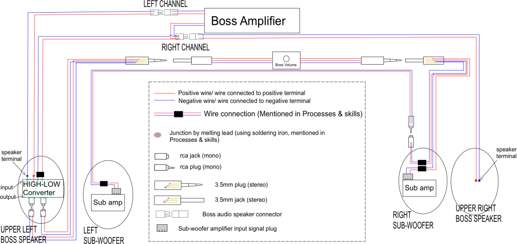
Figure 54: The overall wiring for input signal for sub-woofer
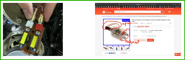
Figure 55: High to Low Converter Figure 56: High to Low Converte
2.3.2. Details:
2.3.2.1. Prepare high to low converter
Firstly I searched for ‘speaker to input converter’ on google. It seemed to be hard to recognize the results in ‘All’ category, and it was hard to find any results by reading the titles. Therefore, I clicked on the tab ‘image’ to see if there was any potential result. As I expected, there are some potential results (being circled in red in Figure 57).
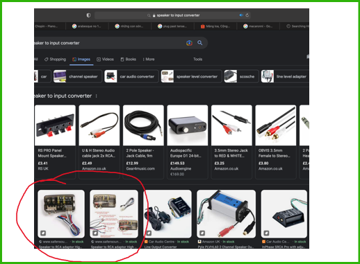
Figure 57
I then clicked on these results to see how they define this type of converter, and I recognized the name for this is high to low (converter) (see red marks in Figure 58 & Figure 59).
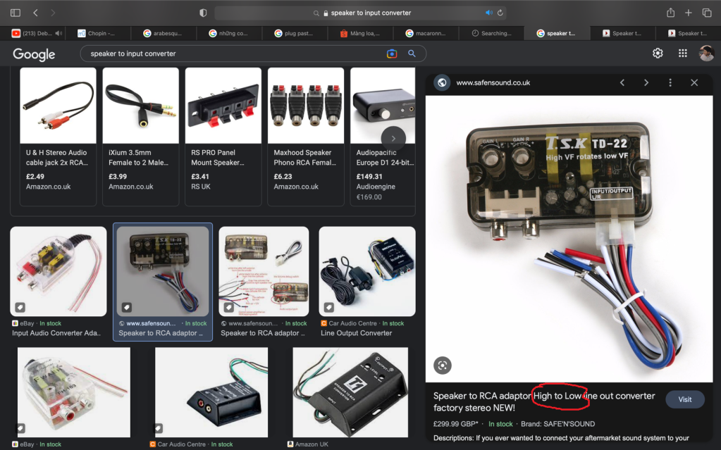
Figure 58
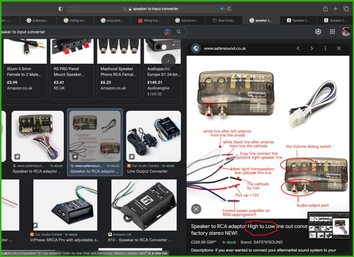
Figure 59
After this, I search for this product on shoppee with keyword ‘high to low’, but the result (product) was not in my country (see Figure 60), so I decided to click on one of them (see Figure 61), scrolling the page down, and see if the shoppee would suggest same product from my country Vietnam so I can buy it faster (see Figure 62).

Figure 60

Figure 61

Figure 62
As from Figure 62, they did suggest a similar product being in my country (the one being marked by red circle in Figure 62). I clicked on it (see Figure 63), and I bought it.

Figure 63
From Figure 63, it can be seen that this converter has 4 input wires, and 2 output plugs (rca plug).
After buying it, I removed the cover so that it took smaller space (see Figure 64). The converter would be situated in the upper left Boss speaker (the one being marked red in Figure 65).
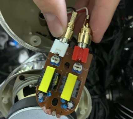
Figure 64
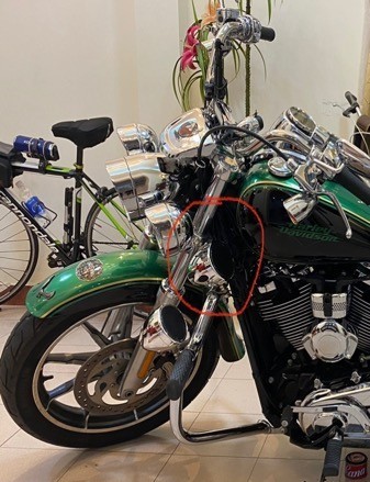
Figure 65
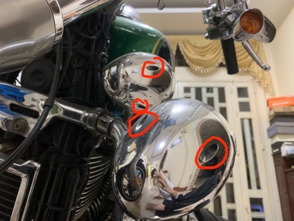
Figure 66
It can be seen from Figure 66 that there were holes where screws situated in. I used phillips driver to unscrew the screws, to open the cabinet (I only opened the upper left one, see Figure 65) to put the high to low converter in.
2.3.2.2. Input of high to low converter
The 4 input wires will be connected to 2 Boss speakers’ channel (left and right) (see ‘Figure 54: The overall wiring for input signal for sub-woofer’ to understand it easier).
Left channel of high to low converter
2 of the input wires were soldered to the terminal of the upper left boss speaker (in which the converter was situated). Figure 67 shows this connection separately from any other connections, Figure 68 shows the soldering stage and the left input of the converter being connected to the upper left Boss speaker driver terminal (being circled red)
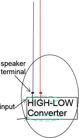
Figure 67

Figure 68
Right channel of high to low converter
The other pair of wires from the input of the high to low converter, instead of being connected to the upper right boss speaker terminal like the left channel one, was connected to right channel output plug from the boss speaker amplifier. (See at RIGHT CHANNEL in Figure 69). The reason for this is that because of the way it was manufactured, it was impossible to lead the wire inside the cabinet of the upper right Boss speaker. The lower right Boss speaker would later be used to store the transformer (mentioned in Dc – dc converter, page 56).

Figure 69
In order to complete this wiring, I first extended this wire by connecting a pair of wires to it (the just above the high to low converter shows this connection, in reality, see Figure 70). This pair of wires was then led out of the cabinet (see Figure 71), wrapped black by heat shrink tube (so that it would not be colorful) (see Figure 71), and connected to the plug.
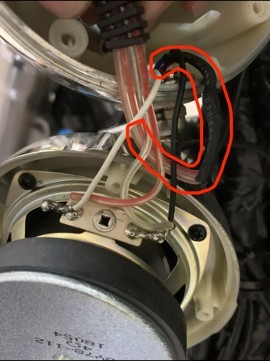
Figure 70
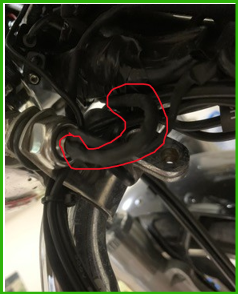
Figure 71
The plug has the plastic cover on the outside, and 2 cooper cores connected to the wires inside.
This plug was being plugged to another plug, so I had to unplug them first (see Figure 72)
I then removed the plastic cover using a specialised tool (see Figure 73) to detach the latches of the cores from the plastic cover (see Figure 74).
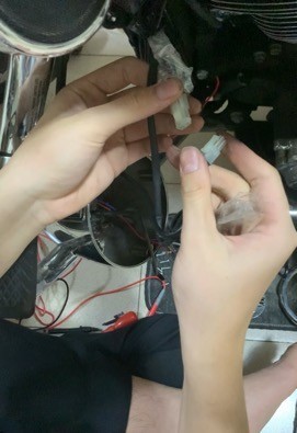
Figure 72
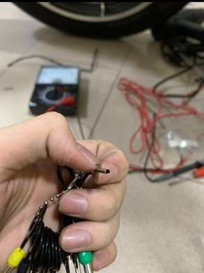
Figure 73
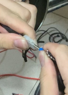
Figure 74
More specfifically, by plug in the tool, the latches would be pushed in so that the core could be pull out from the plastic cover (Figure 75).
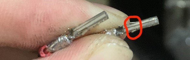
Figure 75
After removing the cover, I opened the latch holding the wire, so that to wire would be twisted toghether, then put back into the latch.
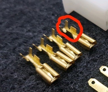
Figure 76
Figure 76 shows the latch holding the wire (marked red). The latch of my jack was similar to this one, but because I had not captured this stage, I used this picture to descirbe it.
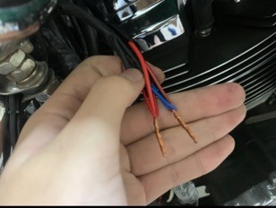
Figure 77
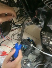
Figure 78
The Figure 77 is not showing the wire that I mentioned, this fugure is from other part, but it could clarify the idea of twisting wires toghether.
After putting the twisted wires back to the latches, I then closed the latches, and used the soldering iron to fix the joint better (see results in 2, 3 in Figure 79).
And then I used black tape to hold two pairs of wires toghether (see 1 in Figure 79).
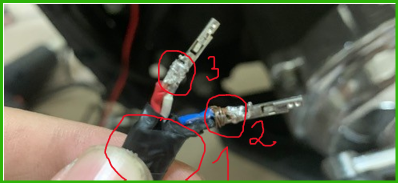
Figure 79
Before puting the core back into the cover, I used the slotted screwdriver to pry the latch up (marked red in Figure 80) so that the core would be held more firmly. And then I put the core back into the cover (see Figure 81).
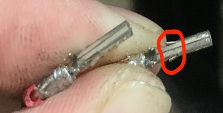
Figure 80
Figure 81
Before plugging the jack into each other, the nilon piece was wraped in (see from Figure 82 marked red) After wrapping it in, I plugged them toghether (see Figure 83 & Figure 84), and warpped the black tape so that the nilon wrap would stay in place (see Figure 85). (Reason for this wrapping is mentioned in Tape wrapping with nylon page 137)
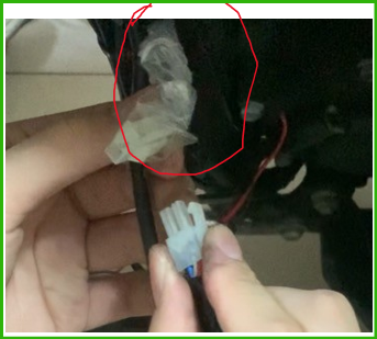
Figure 82
Figure 83
Figure 84
Figure 85
2.3.2.3. Output of high to low converter
After connecting the 4 input wires to 2 channel of boss speaker, I now connected the output of the converter to the input of the subwoofer, passing through a switch. As aforementioned, the cover of the converter was removed to save space.

Figure 86: This shows connections of the output of high to low converter separately from other connections
Two male rca plugs were plugged to the female rca plug of the high to low converter (red mark in Figure 87).
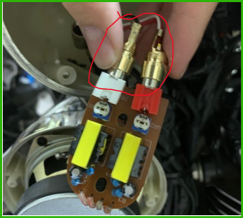
Figure 87
The wires from the male rca plugs (4 wires for 2 plugs) were led out of the cabinet, the ends of these wires were soldered to 3 terminals of a male-type 3.5mm jack (see Figure 88).
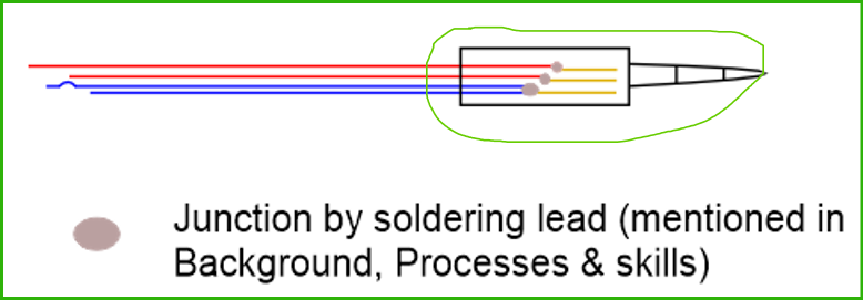
Figure 88
The male-type 3.5mm jack (marked green in Figure 88) would then be plugged into the female-type 3.5mm jack of the volume (marked red in Figure 89).
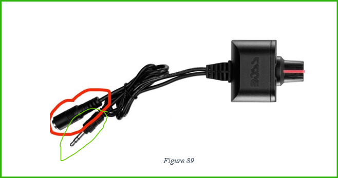
The male-type 3.5mm jack of the volume (marked green in Figure 89) was then plugged into a female-type 3.5mm jack (marked grey in Figure 90).
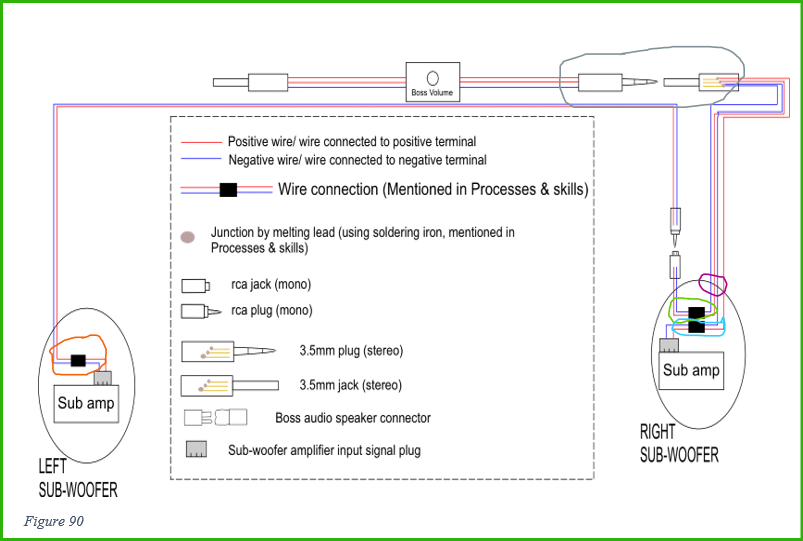
This female-type 3.5mm jack was connected with 4 wires, for two channels (see Figure 90)
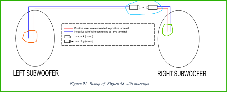
Before any further steps, I will refer back to Figure 48: pair of subwoofer cabinet. Below is the recap of it.
The four wires were led into right subwoofer cabinet (see purple circle in Figure 90 ).
2 of them (for right channel) were connected to the sub-woofer amplifier input signal jack (see light blue circle in Figure 90). Figure 92, number 1 shows the sub-woofer amplifier input signal jack in reality.
2 others were connected to the wire connected to female rca jack that has already been in the right subwoofer before (see green circle in Figure 90 and green circle in the Figure 91). Figure 92, number 2 shows the connection inside the cabinet in reality.
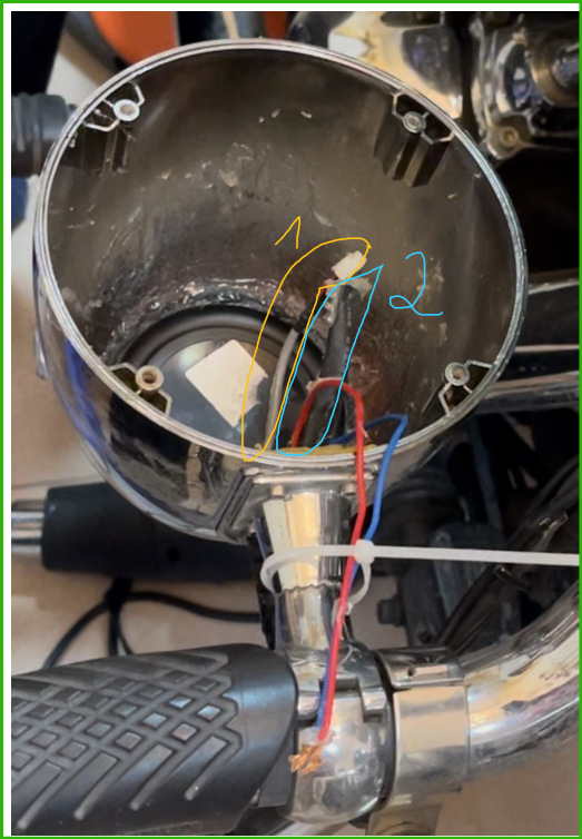
Figure 92
In terms of left sub-woofer, the wires connected to the male rca jack that has already been here were connected to the sub-woofer amplifier input signal jack (see orange circle in Figure 90 and orange circle in Figure 91). Figure 93 shows these in reality, with number 1 showing the male rca jack that has already been here, number 2 showing the wire connection, and number 3 showing the sub-woofer amplifier input signal jack.
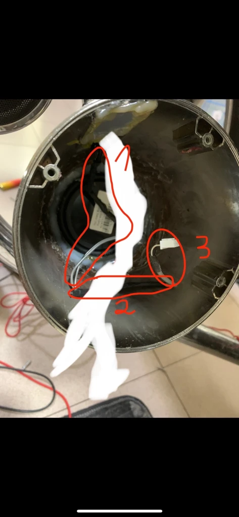
Figure 93
The two rca plug were plugged together (see light blue circle in Figure 91 and red circle in Figure 94)
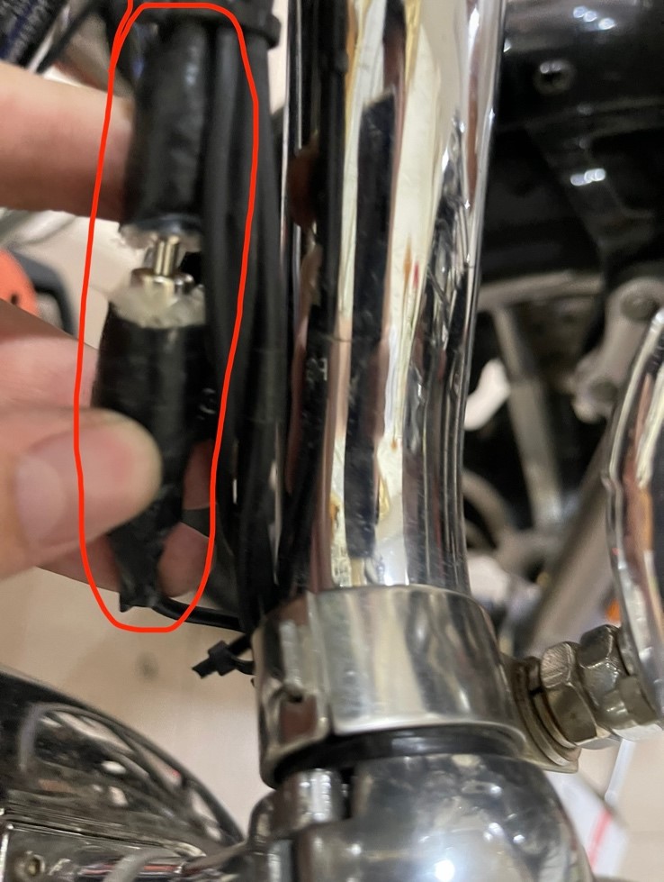
Figure 94