II. Implementation (continued)
2.4. Set up power source for the sub-woofer system (power from battery)
We can have a look at Boss Speaker system, 138 before continue.
2.4.1. Summary:
Firstly, lets have a look at the initial state of power supply for Boss Speaker system in Figure 95 (the SAE plugs are marked MP1 and FP1)
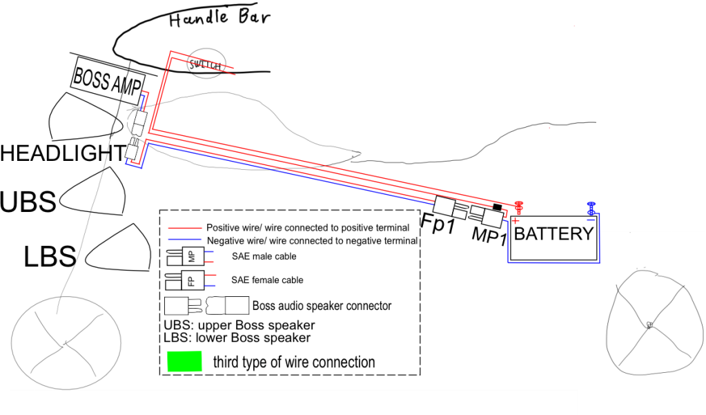
Figure 95: Initial state of power supply for Boss Speaker
Dc – dc converter, page 56: To continue, the input electrical source also played a prominent role in the quality of bass. The voltage of the motor battery was only 13.7V, but that of the amplifier was capable up to 26V; hence, I had to use a pair of voltage transformers, with capability of 100w each (see Figure 96 and Figure 97). The Fp3 is plugged to the Mp3 to extend the wire through the fuel tank, this wire ends at Fp2

Figure 96: Dc-Dc converter wiring

Figure 97: Summary of wiring with dc-dc converter, before connecting to battery.
Initial method, page 76: I connected the electrical input source of two system together (using same line, see Figure 98). In this method, a divider was used (see Figure 99)
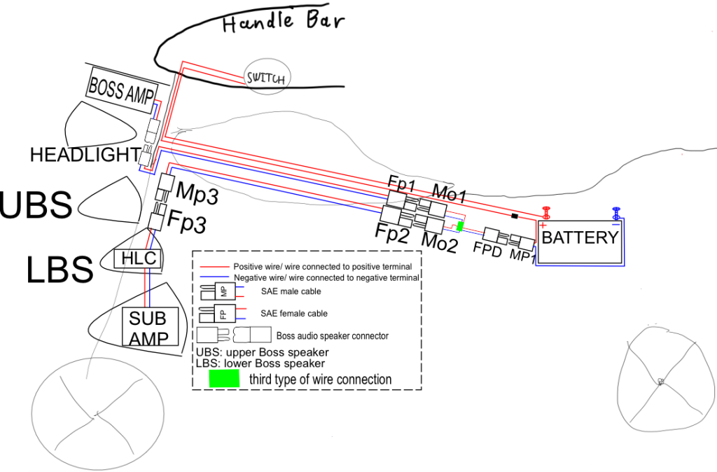
Figure 98: Summary of initial method
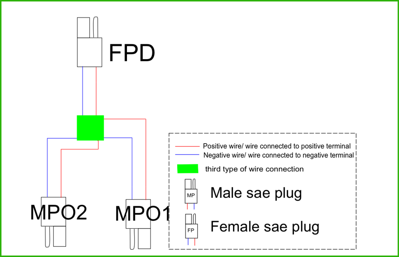
Figure 99: Divider
Final Method, page 80: After some prediction and measurement (see Problem and Solution, page 79), I came up with an idea. Instead of connecting the electrical input source of the sub-woofer system with the electrical input source of the boss speker, I used the relay. Note that I did not use a separate switch, because I wanted the sub-woofer system to be turned on at the same time the boss speaker (mid-treb speaker) is turned on.
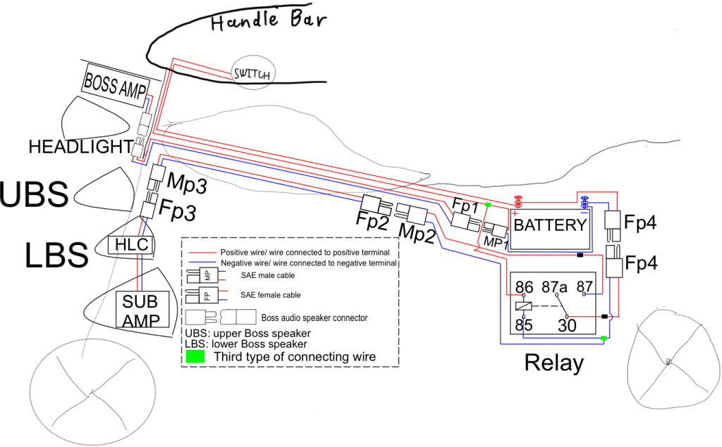
Figure 100: Summary of final method
2.4.2. Dc – dc converter
2.4.2.1. Details and explanation
Voltage transformer explanation: The amplifier was capable of playing from 10V to 26 V, why should I have to convert it? Provided that 13.7V power source was connected, and the resistance of the speaker is 4, the maximum power would be
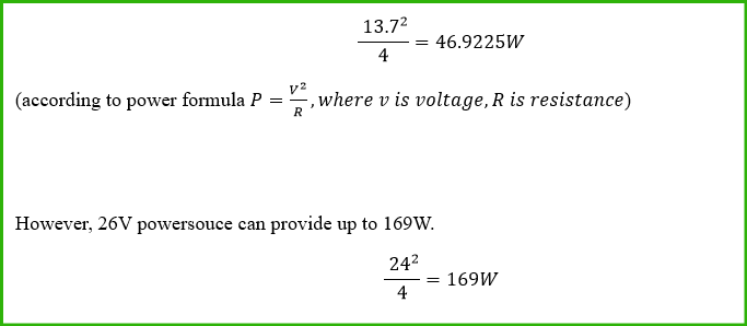
(although my sub-woofer system maximum power was only approximately 80W (40W for each channel)).
2.4.2.2. Assembling:
The two Dc-Dc voltage converter would be situated in the two boss speaker cabinets which were next to the subwoofer (marked red in Figure 101, (I call them lower left and lower right Boss speaker)). The steps for each side were the same, so I only described this process on one side (lower left-channel side)
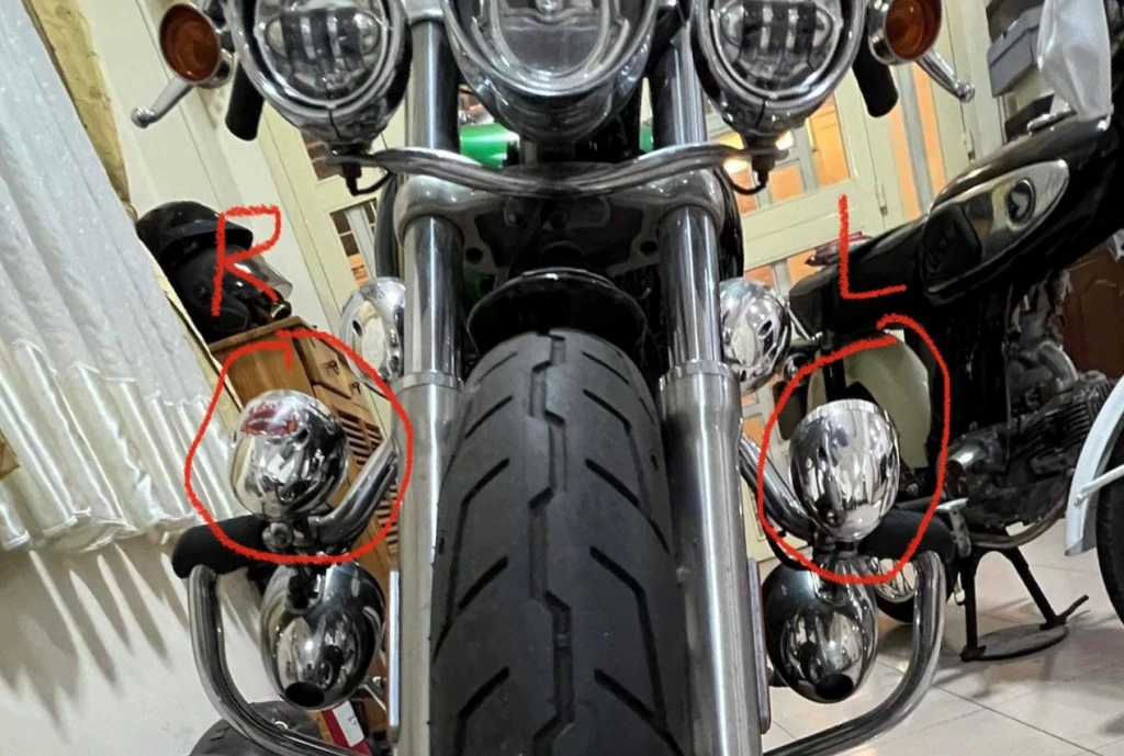
Figure 101
I firstly openned the boss speaker cabinet, this step was similar to the one when I opened the cabinet to put the high to low converter in (see Figure 66 and description below it).
The Dc converter was situated in with totally 2 pairs of wire (see Figure 102 & Figure 103), one is the input, one is the out put , and the wires were led outside of the cabinet via a bolt hole (red circle in Figure 103).
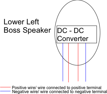
Figure 102
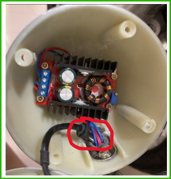
Figure 103
Just after the wires came out of the cabinet, I wraped it by the black heat shrink tube for each pair of wire (see Figure 104) so that the wires would not be colorful. The heat was applied to black heat shrink tube so that it would shrink and fit the wires (see see Figure 104).
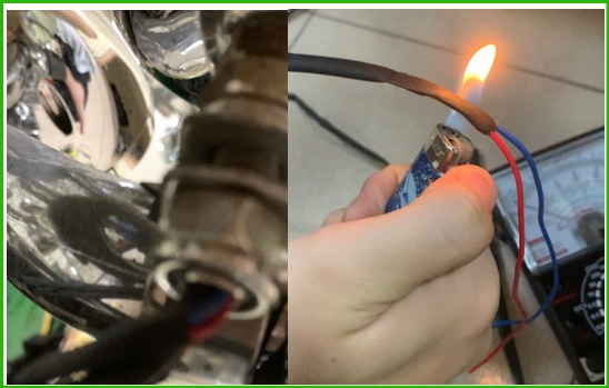
Figure 104
The output pair of wires would then be led to the sub-woofer cabinet via a bolt hole (red circle in Figure 106), to connect to the sub-woofer amplifier power source terminal (see Figure 107). Figure 105 is the summary of these steps.
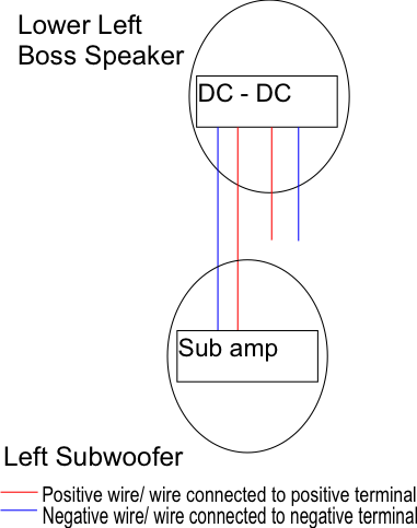
Figure 105
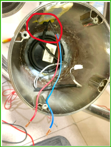
Figure 106
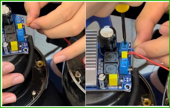
Figure 107
As aforementioned, the same steps were performed on the other side. Figure 108 shows the result.
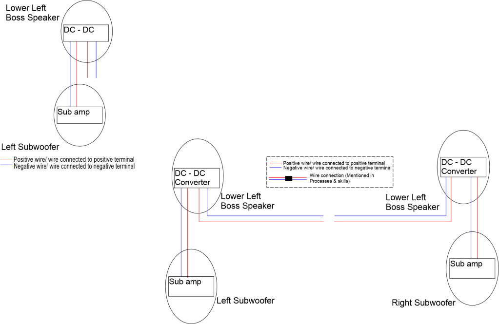
Figure 108
The 2 pairs of input wire of the dc-dc converter from the two sides were led along the engine guard (two red marks in Figure 109), and met at the left side of the fuel tank, then were joined with the female SAE cable FP3 (see Figure 110, cyan box is the junction).
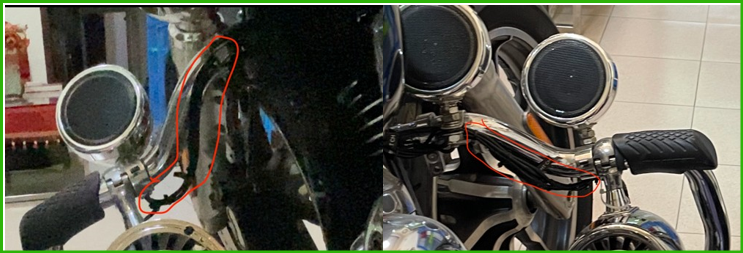
Figure 109
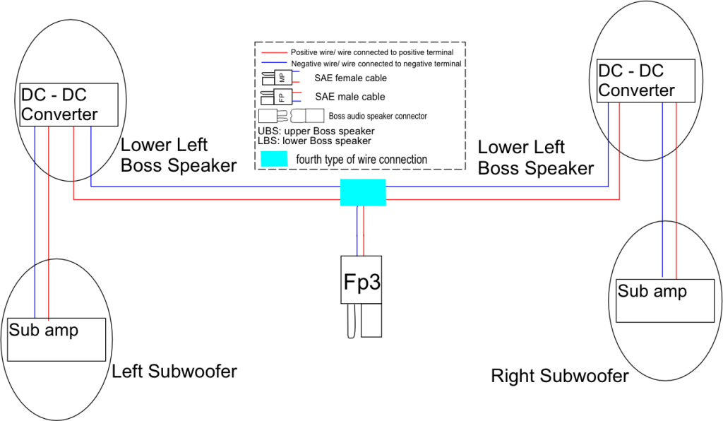
Figure 110
The FP3 is then plugged to the MP3 of the male & female sae cable (see Figure 111 & Figure 112). See also Figure 113.
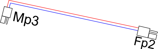
Figure 111: female & male sae cable
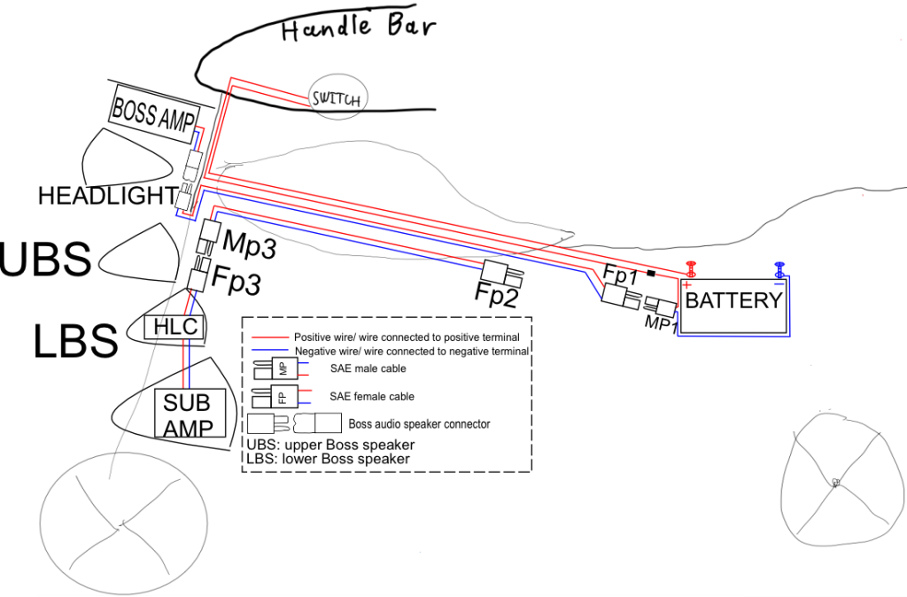
Figure 112

Figure 113
The joint of 2 plugs was wraped by the black tape with a layer of nilon wrap (see Figure 114).
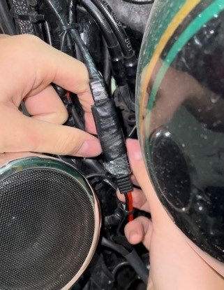
Figure 114
It can be seen from Figure 112 that the male & female sae cable (Figure 111) need to be led through the fuel tank to reach at the seat.
Therefore, the cable would now be led to the seat position through the tank. There was a space inside the frame (chasis) under the tank, but it was full, because many accesories used most of (xem lại cách dung từ) the space. Therefore, in this project, the cable would be led under the tank, but not in the frame.
Seat and tank opening
The seat and the tank would now be opened
(i) Seat removal
- Firstly, I unscrewed the screw at the end of the seat (see Figure 115 and number 4 in Figure 116). The belt would the be pulled to the front (see Figure 117 and number 3 in Figure 118) so that the seat mount below would be unmounted easier.
- The seat was then pulled to the front (see Figure 119 and Figure 120) until the mount and the latch was detached (see Figure 121 and number 2 Figure 122).
- The belt is the pulled back again (see Figure 123 and number 3 in Figure 124). The seat was pulled back thereafter (see Figure 125 and Figure 126) so that the front mount would be detached (see number 1 in Figure 126 and number 1 in Figure 127).
- Finally the seat was taken out by pulling to the front (see Figure 128).
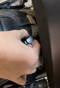
Figure 115
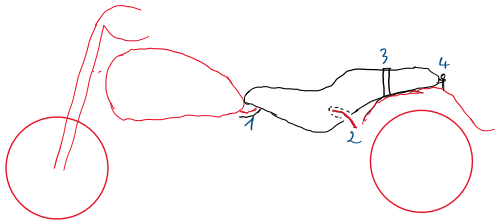
Figure 116
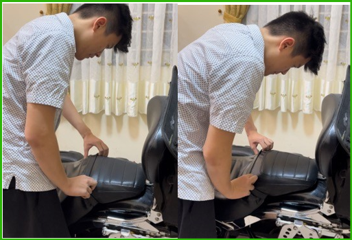
Figure 117
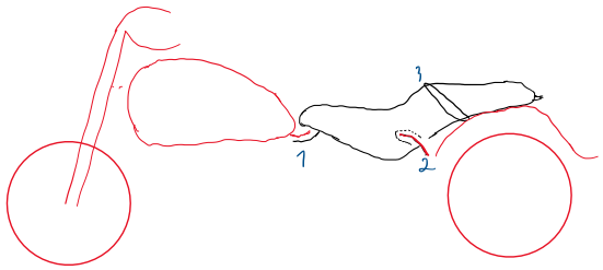
Figure 118

Figure 119
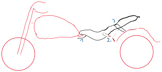
Figure 120

Figure 121
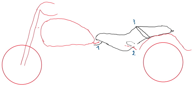
Figure 122

Figure 123
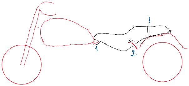
Figure 124
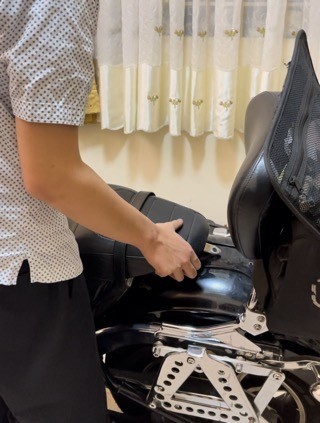
Figure 125
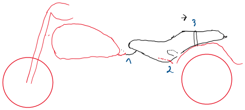
Figure 126
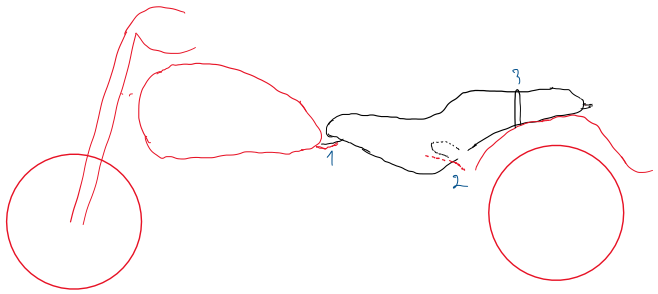
Figure 127

Figure 128
(ii) Tank
(a) Unscrewing tank
After opening the seat, the fuel tank would be lift up to lead the wire under it.
The fuel tank is hold by two pairs of bolts and nuts, one in front and one at the back (just below the seat). This required two spanners13, 9/16-inch ring spanner (see Figure 129) (for bolt (see 2 in Figure 131)) and 14mm ring spanner (see Figure 130) (for nut (see 1 in Figure 131)).
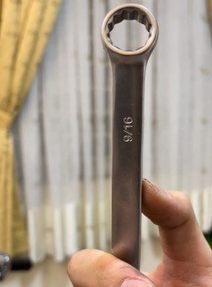
Figure 129: 9/16-inch ring spanner

Figure 130: 14mm ring spanner
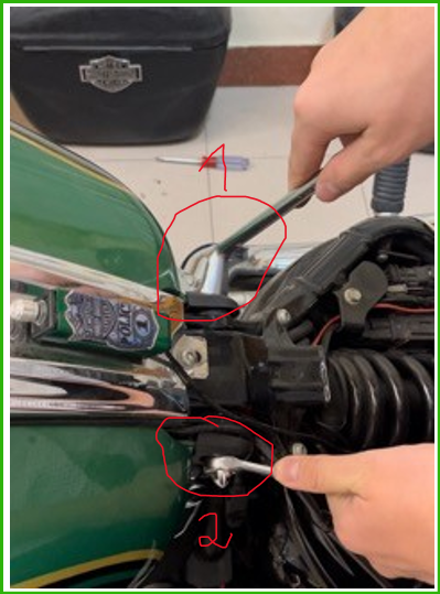
Figure 131
Firstly, the pair at the back would be unscrewd slightly so that the tank would be lift easier (see Figure 131).
After the bolts and nuts at the back were unscrewd slightly, the front bolt and nut would be unscrewd completely (see Figure 132), taken out (see Figure 133).
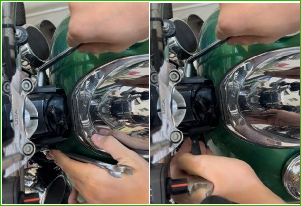
Figure 132
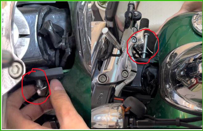
Figure 133
The fuel tank was then lifted up (see Figure 134).
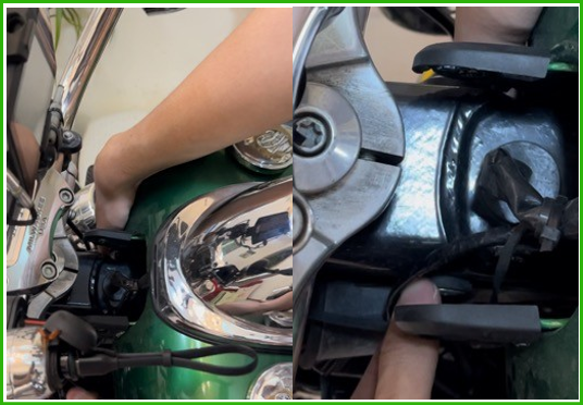
Figure 134
(b) Wire leading
The figure below would show the cable wrapped black was led in (red marks in Figure 135) and taken out at the end of the tank (red mark in Figure 136).
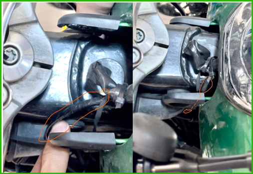
Figure 135
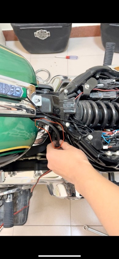
Figure 136
After this, the bolts and nuts were re-screw by just reversing the uncrewing steps (page 71).
Leave a Reply