

I. BACKGROUND:
1. Situation:
I and my father own a motorcycle Harley Davidson Softail Low Rider and we enjoy listening to songs during our ride. My motorcycle had a Boss speaker system on it, but it was not built to produce good bass (low frequency sound). So, I need to have a pair of sub-woofers to increase the amplitude of bass of the overall sound, especially essential for my playlist (including songs that require good bass).
In general terms, speakers produce sound and a subwoofer is a type of speaker that produces low frequency sound. It requires more power than the ones producing middle or high frequency because our ears are more sensitive to the high frequency.
I have found no subwoofer in my motorcycle model (2018 Harley Davidson Softail Low Rider). Sub-woofers are only applied for another Harley Davidson model – Touring. However, I and my father did not choose the Touring model due to its overwhelming size and weight, which are not suitable for traffic in my country-Vietnam. I also could not buy the sub-woofers of Harley Davidson model – Touring to mount for my motor because of the different design. Therefore, I decide to create a pair of sub-woofers in my own way.
2. Objective:
- It must maintain the good quality and amplitude of the input signal of the existing boss speakers and make the input signal quality of the (added) sub-woofers as good as that of boss speakers.
- Boss speakers and sub-woofers can be turned on/off at the same time.
- The appearance and the positions of the sub-woofers must be harmonious with those of the existing bass speakers, it should not destroy the original design. The positions must ensure that the sound of the sub-woofers is heard as well as the existing bass speakers and be convenient for electrical connection.
3. Note:
- Mid-treb speaker = Boss speaker, is an existing speaker system that has been assembled before this project on the motorcycle.
II. Implementation:
1. Details
1.1. Set up Sub-woofer cabinets and the inside:
I outline the process of setting up the sub-woofer as below:
1.1.1. Identify suitable sub-woofer position: to meet the requirement as above mention

Figure 1: Position of subwoofer (this is captured after having done the project)
1.1.2. Sub-woofer cabinets: Prepare a sample cabinet for testing, and a pair of official cabinets.

1.1.3. Pair of sub-woofer drivers: Finding a suitable one (in terms of size and power, try to fit it in the cabinet)

Figure 3: This shows a speaker driver.
1.1.4. Pair of sub-woofer Amplifiers: Finding a suitable one (in terms of size and power, try to fit it in the cabinet)
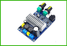
Figure 4: This shows a sub-woofer amplifier.
1.1.5. Pair of passive bass radiators: Finding a suitable one (in terms of size, test with different size for the best performance, try to fit it in the cabinet)

Figure 5: This shows a passive bass radiative
In this section, I would try to test which bass radiator suit the cabinet the most, in terms of size, design, performance. I used the left GHS (see Error! Reference source not found.) to test.
1.1.5.1. First test
In Figure 6, the cyan dotted line passing through the top of the amplifier and cutting the cabinet shows the height of the speaker and the amplifier when the cabinet is closed. The yellow dotted line is the range for the passive radiator to vibrate (approx. 1cm each side). After measurring 90mm was roughly the maximum diameter which satisfy the requirement for vibrating (red dotted line).
But to make sure nothing went wrong such as the rubber suspension of the passive bass radiator, I used 85mm passive radiator (see Figure 7)

Figure 6

Figure 7

On testing, I found 3 problems:
There was some high-pitched noise coming from the passive radiator, and as I tried to use my finger to knock on it, there was a high-pitched noise.
The bass radiator was moving too much as it was expected which may damage the suspension, this also explain the reason for the first problem.
With this design, the hole was quite large, and the edge, when being drilled, ofcourse, would not be perfectly shaped, there might be some scratches, and the bigger the hole, the easier the scratch would be seen.
Solution:
Therefore, I decided to add some mass on the passive radiator to restrain its movement, the mass should have a plastic layer outside so that it would not generate high-pitched noise, the size of the passive radiator was kept the same. A smaller hole would be drilled.
1.1.5.2. Second Test
On this sample cabinet, because I has already drilled a big hole, I took the part of the cabinet that was drilled, and drilled a small hole on it (see Figure 8), and attached it back to the cabinet (where I previously drilled) by hot melt glue gun (see Figure 8).

Figure 8: Drilling in second test
After this, I added mass on the passive radiator (see Figure 9).

Figure 9
I tested by choosing a song with a lot of bass, I turned the bass volume to maximum(see Figure 10).

Figure 10
Conclusion:
This test appeared to be perfect. So after this I would drill a small hole in the official cabinet, assemble the passive radiator in. I did the similar steps with both cabinets.
1.2. Assembly Sub-woofer cabinet:
All the above steps were done on a sample cabinet. After all, the parts that has been tested and adjusted to fit the sample cabinet would be assembled into the official cabinets.

1.3. Set up input signal for the sub-woofer system (music signal):
Connecting signal between the boss speakers and the sub-woofer amplifiers. However, the output voltage of the speakers was too high compared to the limit of the input of the amplifiers, and to address this issue, the high to low signal converter has been used.
1.3.1. Summary
The design of input signal of sub-woofer amplifier:
Situation: Given that I had as follows:
- A MP3 with its output was 50mW.
- 4 boss speakers with only one mid-treb amplifier
- 2 sub-woofer speakers with 2 sub-woofer amplifiers
- Maximum amplified signal of mid-treb amplifier is 100W.
- The maximum input power of a mid-treb amplifier was 50mW.
- The maximum input power of a sub-woofer amplifier was 25mW.
The first design:

Figure 12: The first design of subwoofer signal input.
The output of the MP3 device was 50mW. With the method, input power of the mid-treb amplifier would be 25mW, and that of the two sub-woofer amplifiers would be 25mW. It meant input power of the mid-treb amplifier, and the two sub-woofer amplifiers would only account for 50% of the MP3 output each, and therefore, the loudness of the Boss system and subwoofer system will both decrease by 50%.
The second design:

Figure 13: The second design of subwoofer signal input
With this design, input power of the mid-treb amplifier would be 50mW, and that of the two sub-woofer amplifiers also would be 50mW. It meant the input power of the mid-treb amplifier, and that of the two sub-woofer amplifiers could account for the equivalent of 100% of MP3 output each. It also reached the maximum limit of the input voltage of a mid-treb amplifier (50mW), and that of a sub-woofer amplifier (25mW).
The output voltage of the speaker is too high compared to the limit of the input of the amplifier, and to address this issue, I used the high to low signal converter.
Also, I have connected one sub-woofer amplifier to a left boss speaker and another sub-woofer amplifier to a right boss speaker via high to low converter, so in case the left boss speaker or right boss speaker was off (due to the arrangement of the song), there would still be a working sub-woofer amplifier.
Comparing the two designs above, of course, I chose the second one.
The overall wiring for input signal for sub-woofer

Figure 14: The overall wiring for input signal for sub-woofer

1.4. Set up power source for the sub-woofer system (power from battery):
Connecting the sub-woofers to motor battery via a relay so that when the switch of the boss speaker (mid-treb speaker) was turned on, the sub-woofer was also turned on.
In this section only, HLC in diagram stands for DC-DC converter
1.4.1. Summary:
Firstly, lets have a look at the initial state of power supply for Boss Speaker system in Figure 17 (the SAE plugs are marked MP1 and FP1)

Figure 17: Initial state of power supply for Boss Speaker
DC-DC Converter: To continue, the input electrical source also played a prominent role in the quality of bass. The voltage of the motor battery was only 13.7V, but that of the amplifier was capable up to 26V; hence, I had to use a pair of DC-DC converter, with capability of 100w each (see Figure 18 and Figure 19). The Fp3 is plugged to the Mp3 to extend the wire through the fuel tank, this wire ends at Fp2

Figure 18: Dc-Dc converter wiring

Figure 19: Summary of wiring with dc-dc converter, before connecting to battery.
1.4.1.1. Initial Method
I connected the electrical input source of two system together (using same line, see Figure 20). In this method, a divider was used (see Figure 21)

Figure 20: Summary of initial method

Problem:
A problem occurred. When I turned on the volume, the sound from subwoofer got distorted and I predicted that the load for to amplifiers on one line was too much, especially, this line is very long (as it has to pass through a switch situated far away from the battery), which means the resistance of the wire of this line is quite a lot (see Error! Reference source not found.). When I measured the voltage of the subwoofer while it was working, the voltage fluctuated around only 10.5V instead of 13.7 volt as expected, which means the resistance of the wire (which is in series with the subwoofer and Boss speaker systems) is too high compared to the subwoofer and Boss speaker systems. (see Figure 22 for diagram and explaination)

Figure 22
1.4.1.2. Final Method
To solve the Problem: page 14 (from the First Method), I came up with an idea. Instead of connecting the electrical input source of the sub-woofer system with the electrical input source of the boss speker, I used the relay. Note that I did not use a separate switch, because I wanted the sub-woofer system to be turned on at the same time the boss speaker (mid-treb speaker) is turned on.

Figure 23: Summary of final method
2. Overall results
Before:

After:


The end