II. Implementation (continued)
2.4. Set up power source for the sub-woofer system (power from battery) (continued)
2.4.3. Initial method
I connected the electrical input source of two system together (using same line))
Before this project, there was no subwoofer, Figure 137 shows the power supply for Boss speaker system before installing subwoofer.

Figure 137
I then made a divider (see Figure 138 & Figure 139) and connected to the Boss speaker system and Subwoofer system (see Figure 140 & Figure 141). It can be seen in Figure 140 that the FPD was connected to the MP1; MO1 and MO2 are connected to FP1 and FP2 respectively. This means Boss speaker system and subwoofer system would use the same source from MP1.


2.4.3.1. Problem and Solution
As aforementioned, a problem occurred, when I turned on the volume, the sound from subwoofer got distorted and I predicted that the load for to amplifiers on one line was too much, especially, this line is very long (as it has to pass through a switch situated far away from the battery), which means the resistance of the wire of this line is quite a lot (see Figure 140). When I measured the voltage of the subwoofer while it was working, the voltage fluctuated around only 10.5V instead of 13.7 volt as expected, which means the resistance of the wire (which is in series with the subwoofer and Boss speaker systems) is too high compared to the subwoofer and Boss speaker systems. (see Figure 142 for diagram and explaination)

2.4.4. Final Method
2.4.4.1. Relay:
How does realy work: Relay, page 80.
Due to the aforementioned problem of initial method (see Problem and Solution, page 79), but I wanted the subwoofer to be turned on at the same time the mid-treb system was turned on, so I installed a relay, which uses the current from the electrical input source of Boss speaker as a signal to turn on the relay which connect current directly from the battery to the subwoofer system. Therefore, sub-woofer system and Boss speaker system would use separate lines, which would reduce the load (current intensity) on each line.
Figure 143 shows relay overall wiring.

How does relay work can be found at Relay, page 102.
The relay was situated in the under-seat area. There are 4 wires from the relay, two blue and two black

The wire was connected to the terminal by soldering (the pictures for this are not available), and then I used the hot melt glue gun to cover this position so that water could not come in. The relay was then wrapped by the black tape with a piece of nylon inside to resist water and or the next time I open, the relay would not be sticky.

Explanation of the wiring (refer to Figure 143: Relay overall wiring)
- The MP4 is the Sae battery connector, it has 2 ring to connect to the battery terminals
- The FP4 is connected to the MP4, which is connected to the battery terminals. The posstive wire from FP4 is connected to terminal 30 of the relay.
- The negative wire from FP4 is connected to terminal 85 of the relay and to the negative wire of MP3
- Wire from the output of the switch (of the Boss speaker) is connected to terminal 85 of the relay
- Wire from terminal 87 is connected to the positive wire of MP2
How it works:
When the switch (of Boss speaker) is turned on, the electromagnetic connected terminal 85 and 86 is activated, this will attract the armature (iron bar) and connect the terminal 30 to the terminal 87 (normally open terminal), and transfer current to dc-dc converter (and then to sub-woofer amplifier).

Because the MP4 sae battery connector need to be connected to the battery terminals, the steps below shows how the two rings of MP4 sae battery connector are connected to the battery terminals
2.4.4.2. Main fuse removal
Firstly, I opened the left battery cover side pannel by unscrewing a screw using a 5/32-inch hex key (see Figure 146), and pull the side pannel out (see Figure 147).

To diconnect the main fuse I pulled the fuse box out of its position, then pulled the cap out, then pulled the main fuse out (see these steps described in Figure 148, the main fuse is the big orange thing). NOTE that I turned on the ignition switch before disconnecting the main fuse.

Reasons for turning on the ignition switch:
Before unplugging the fuse, I had to turn on the ignition switch because this would disable the alarm system. If the ignition switch was not on first, the alarm would go on. (This was what I was reccomended by an engineer – Tuan Khanh, at Harley Service in Saigon, South Vietnam).
Reasons for removing this fuse:
Because I had to turn on the ignition switch before disconnecting the battery terminals, if I did not remove the main fuse first:
- When the negative terminal was pulled out, it might keep flickering, and the current into the system keep flickering, meaning the energy keep increase and decrease rapidly, which was not good for the system.
- Secondly, I took some time to open the negative terminal, so it might consume a certain amount of battery capacity if I do not remove the fuse first.
After finishing disconnecting the main fuse, I moved on opening the baterry terminal.
Firstly, I opened the right battery cover side pannel by unscrewing a screw using a 5/32-inch hex key (see Figure 149), and pull the side pannel out (see Figure 150).

The negative terminal would be open first then the positive terminal.
2.4.4.3. Open Negative Terminal
Reason for opening negative terminal before positive terminal:
- The negative terminal would be open first then the positive terminal, not only because their positions being convenient for this opening order, but also because the negative terminal was connected to the whole frame (chasis). Therefore if I opened the positive terminal first, the screw driver (which is in contact with the positive terminal) might touch frame or anything that was connected to the frame, which would lead to short circuit.
- The main negative hold the plastic cover, which cover the positive terminal, therefore I had to open the negative terminal first
The negative terminal screw was uncrewed, using the 10mm spanner and a phillips screw driver. I firstly used the 10mm spanner to unscrew the screw as this require quite a lot of torque, and then after it got easier I used the phillips screwdriver to increase the speed (see Figure 151).

2.4.4.4. Open Positive Terminal
The positive terminal is covered by a plastic cover, so we had to remove this cover first (see Figure 152, NOTE that this figure is taken from some step a head, not from initial step, so that the plastic cover can be seen easier.).
There are some stuff (wire, plastic cap) that prevent he plastic cover to be pulled out so I removed or detached these first.
The plastic cover is held by 3 latches, so I had to detach 3 latches.

Removing some stuff
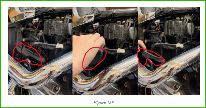
A cap in front of the plastic cover would be removed bu pulling out (see red marks in Figure 153).
The wire latch (being circled red in Figure 154) would be opened first (Figure 155), then the abs wire would be pulled out, then detached from the plastic cover piece’s latch (see Figure 156).


After this, I unplugged the connectors (number 1 in Figure 157), then I pushed the connector that was attached to the plastic cover piece (number 2 in Figure 157, my finger was pushing it) to detach it (number 3 in Figure 157), then pulled it out (number 4 Figure 157).

After all cables were moved away, there were three latches holding the plastic cover piece needed detaching.
First latch
The two pictures in Figure 158 illustrates the first latch holding the plastic cover piece and it being detached.

Second latch
I then detatched the second latch. Figure 159 shows the position of the second latch. In Figure 1601. 2.
Figure 160, number 1 shows the diagram of the structure of the latch and how to detach them, number 2 shows how it looks like after detaching.


Third latch
The final latch was detached (see Figure 161) by
- Step 1:pushing the plastic cover piece (numbered 1 in Figure 161) so that the latch was not in the holding position,
- Step 2: I then used the slotted screwdriver to pry the holder out (number 2 in Figure 161)
- Step 3: I then pulled the plastic cover piece out (see Figure 162).


Figure 163 shows the latch. Figure 164 shows that I was pushing th plastic cover piece and using the slotted screwdriver to pry the latch (step 1 and 2). Figure 165 shows that the latch was detached.


After pulling the plastic cover out (see Figure 166), the positive terminal could then be reached. I then used the phillips screwdriver to unscrew the screw (see Figure 167)


2.4.4.5. Conneting positive ring
The positive ring of the SAE plug (being circled red in Figure 168) was connected to the positive terminal of the battery by putting the screw through the ring (toghether eith other existed ring (the same asFigure 171)), and then re-screw the positive terminal (see Figure 169).

2.4.4.6. Reversing
I then reversed all the steps in Open Positive Terminal section, starts from page 85 ends at page 95)
2.4.4.7. Connecting negative ring
After that, the black ring of the SAE plug (being circled black in Figure 170) was attached to the negative terminal by putting the screw through this ring (toghether with other existed ring: see Figure 171), and then I re-screwed the negative terminal (see Figure 172).

After finishing connecting all the wires, I then organized them in the most convenient way.
The relay was also fixed in a safe position by two black nylon cable ties. (see Figure 173: 1 and 2 were the two black nylon cable ties, 3 was the relay)

2.4.4.8. Voltage testing
At this moment I would return to the voltage converter to test it.
Because this sub-woofer would works on the engine runing, and when the engine was running, the voltage supplied to the transformer was higher(13.7V compared to 12V), therefore the voltage converter was adjusted to supply 24V to the subwoofer when the voltage converter was supplied al voltage of 13.7V (engine on idling). NOTE that the voltage the charger of the engine supply was always approximate 13.7V on different engine speed (rpm- round per second)
To perform this (the steps below is for one side – left channel, the other side would follow the same steps):
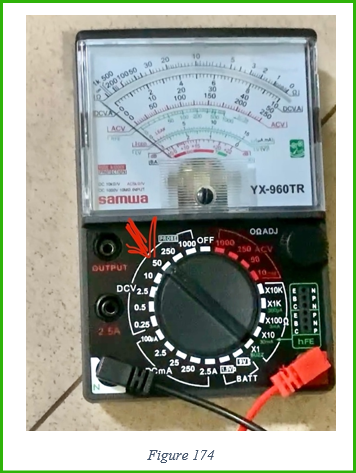
I needed a multimeter, and it was set to the DCV 50V (Direct circuit voltage, on the scale 50V, maximum of 50V) (see Figure 174)
I firstly measured the input voltage of the voltage converter (see Figure 175) to make sure the relay was working normally (13.7V as expected: see Figure 176).

I measured the voltage of the output of the transformer (see Figure 177) and adjusted the adjusting screw using a slotted screw driver (see Figure 178) until the multimeter reads 24V (see Figure 179).


2.4.4.9. Final test and assembly
I then turned the Boss switch on, turned a song on, and tested if the sub-woofer worked, NOT testing the sound. It worked.
I then closed the sub-woofer cabinets on both sides, using the phillips screw-driver (see Figure 180), and then close the covering ring (see Figure 181).
I also closed all Boss speaker cabinet.


I finally tested the whole system, with 4 songs: “Can’t help falling in love with you” – Elvis Presley, “You’re my heart you’re my soul”-Modern Talking, “Booty bounce”-Tukamo & Taio Cruz, “Jingle Bell”-JJ Little and the Holly Dollies. All was working really good.
2.5. Tidy up:
I connected the main fuse and close the battery left side cover by reversing steps in Main fuse remov page 83.
I reversed the steps in Open Negative Terminal page 84 to close the battery right side cover
I then rescrewed the fuel tank by reversing steps in Unscrewing tank page 71.
I then reassembled the seat by reversing the steps in Seat removal page 64.
3. Overall results
Before: (Recap of Figure 7: This shows the position of the sub-woofer being marked red. Page 4)

